

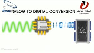
Introduction to USB 1404 Data Acquisition Card
The USB-1404 Data Card is used for reading various sensors and operating electrical actuators. This data acquisition module is capable of reading analog and digital signals across a wide range of standard voltages. The digitized values of the analog inputs are transmitted via the USB port to LabVIEW software or a Windows-based application based on issued commands, where they are displayed and processed.


Capability of sampling at speeds up to 50,000 samples per second in single-channel differential mode or single-ended output.

Capability of 16-bit high-precision sampling.

In the Data Card USB 1404, all circuit components are fully implemented in a completely integrated design.

All sampled data is stored on the computer with precise timestamps and can be analyzed and reviewed in LabVIEW software.
Applications of USB-1404 Data Card
- Reading various types of sensors
- Ability to operate various electrical actuators
- Reading current input from 4 to 20 mA
- Generating analog and digital signals with desired values
- Reading analog and digital signals with different voltage levels

USB DAQ 1404 technical specifications
Digital Input | |
4 | Digital Input |
2 | Input captures |
50 KHz(Max) 10 KHz(Min) | Input captures frequency |
Digital Output | |
2 (12V – 5 Amp) | Relays |
4 | Output |
4(50 KHz) | PWM |
2 | Counters |
Physical Specification | |
16 cm | Lenghth |
11.6 cm | Width |
4.5 cm | Hieght |
Screw Terminal | I/O Connector |
-20 to +80 C | Operating Temperature |
General | |
Product Family | |
USB 20, RS 232 | Interface Type |
Windows | Operating System |
+5V(USB), Adaptor 12V | Source Voltage |
Analog Input | |
8 Channels | Single–Ended & differential–Ended |
12 bits , 16 bits | A/D Converter Resolution |
50 Ks/s (Max) | Sample Rate |
2 Channels | Current |
16 bits & 32 bits | Counter |
Analog Output | |
2 | Number Of DAC Channels |
12 bits | Resolution |
0V – 5V | Range |
0.1 – 1000 Hz | Signal Frequency |
Software Capabilities of Datalogger USB 1404
- Ability to modify and monitor the status of digital inputs and outputs
- Ability to view and control relays
- Equipped with numeric displays with on/off functionality for monitoring Capture Frequencies, Counters, and 4-20mA Current
- Includes a selection and configuration section for determining Duty Cycle for PWM signals
- Manual adjustment of voltage and waveform type for DACs

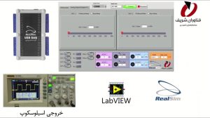
- Equipped with a real-time graphing interface for ADCs
- Ability to save ADC data files in Excel format

Hardware Features of the USB 1404 Data Acquisition Card
- Equipped with a relay featuring a noise suppression circuit based on an optocoupler, ensuring complete elimination of input noise.
- Includes 4 ADC channels of Σ-Δ (Sigma-Delta) type.
- 16-bit sampling accuracy.
- Adjustable sampling rate.

Videos of Data Card USB 1404
Comments are closed.